Finding your rooftop flooded because a water tank overflowed is a costly and frustrating mistake that wastes precious resources. You can prevent this damage instantly by learning how to make a water tank overflow alarm at home using simple, low-cost parts.
This guide shows you exactly how to build reliable alarms ranging from basic transistor circuits to wireless solar systems. You will discover safe wiring methods, how to position sensors correctly, and ways to stop false alarms before they start.
Build a Simple Transistor Alarm Circuit

This design is the most reliable starting point for beginners who want a functional alarm without complex electronics. It uses a single BC547 NPN transistor as an electronic switch that activates only when water bridges two metal probes.
Position the Sensor Probes Correctly
You must mount two stainless steel rods or insulated copper wires inside your tank just below the overflow pipe. Expose only the very tips of the wires and keep them 1 to 2 centimeters apart so water can bridge the gap easily. One probe connects to the positive supply path while the other links to the transistor base through a resistor.
Wire the BC547 Switching Mechanism
Follow this specific wiring order to ensure the circuit functions safely and effectively:
* Connect the emitter pin directly to the ground or negative terminal.
* Attach the collector pin to one terminal of your chosen buzzer.
* Link the other buzzer terminal to the positive side of a 9V battery.
* Route the base pin to the first probe wire using a 1kΩ resistor.
* Connect the second probe wire to the same side as the buzzer positive connection.
Pro Tip: Never skip the 1kΩ resistor on the base pin because excess current will destroy the transistor instantly.
Test the Circuit Before Installation
Submerge both probe tips into a glass of tap water and turn on your power switch to verify operation. The buzzer should sound immediately if your connections are correct and the transistor is oriented properly. If silence persists, check your battery charge level and ensure the flat side of the transistor faces the right direction.
Create a Direct Battery Buzzer Setup
Skip the transistor entirely if you need the absolute simplest possible conduction circuit for temporary use. This method relies on water itself to close the electrical loop between a battery and a buzzer without any switching components.
Assemble the Minimalist Wiring
Gather a 9V battery, a switch, a buzzer, and two wires with exposed tips to build this direct system. Connect the battery positive terminal to the switch, then run the output to the buzzer and finally to the first probe wire. Complete the loop by connecting the second probe wire directly back to the negative battery terminal.
Add a Visual Alert Indicator
Install a green LED with a 1kΩ resistor across the buzzer terminals to provide a visual cue alongside the sound. This light will glow only when water completes the circuit and activates the buzzer simultaneously.
⚠️ Warning: This design sends current through the water continuously when active so you must use low voltage DC under 12 volts only.
Install a 555 Timer Indicator System

Upgrade to a smarter feedback loop using a 555 timer IC that controls both audible and visual alerts based on precise water levels. This configuration allows for dual-level monitoring where different probes trigger specific responses.
Configure Dual Level Probes
Place two probes at different heights within your tank to distinguish between safe levels and overflow conditions. Connect the bottom probe to the ground while linking the top probe to Pin 2 or the trigger input of the 555 timer chip. Water rising to the top probe pulls the trigger low and activates the timer logic.
Set the 555 Timer Logic
Wire the integrated circuit pins according to these specifications for stable operation:
* Pin 1 connects to ground.
* Pin 2 receives the trigger signal from the top probe.
* Pin 3 outputs the signal to a transistor base via a 1kΩ resistor.
* Pin 4 connects to Vcc to keep the reset function active.
* Pin 5 links to ground through a 0.1µF capacitor for stability.
* Pin 8 connects to the 9V positive supply.
Monitor Safe and Full Levels
Connect a green LED with a resistor from Vcc to ground so it stays lit when the tank is not full. The red alarm LED and buzzer will only activate when the water triggers the timer, turning off the green light to show the status change clearly.
Create a Wireless Remote Alarm System

Hear alerts from inside your house by building a wireless version that uses 433 MHz RF modules to transmit signals. This setup eliminates long wire runs and allows you to monitor roof tanks from your kitchen or bedroom.
Build the Waterproof Transmitter Unit
Seal two copper rods inside a plastic enclosure rated IP65 or higher to protect electronics from rain and humidity. Position the lower rod at the fifty percent mark and the upper rod at the overflow level then connect them to the data inputs of a 433 MHz transmitter module. Power this unit with a 3.7V lithium-ion battery to ensure long-term operation.
Power with Solar Energy
Attach a small 1 to 2 watt solar panel with a charge controller to keep the battery charged indefinitely. This solar integration makes the system ideal for remote roof locations where changing batteries is difficult or impossible.
✅ Solar Benefit: A properly sized panel allows the system to run forever without manual battery replacements.
Set Up the Indoor Receiver
Place a receiver module powered by USB or battery in your living area and wire three LEDs for status updates. Use a green LED for the fifty percent signal, a blue LED for the full tank signal, and a red LED to indicate the system is powered on.
Install a Mechanical Float Alarm
Choose a mechanical float switch if you prefer a solution with no electronic circuits or soldering required. These commercial style devices use physical movement to trigger a switch when water reaches a certain height.
Mount the Float Sensor
Attach the float mechanism to the inside wall of your tank just below the overflow pipe outlet. Ensure the float moves freely up and down without hitting tank walls or pipes that could cause it to stick.
Connect to a Control Unit
Run the cable from the float switch to a dry mounted control box located in your garage or utility room. Plug this unit into a grounded wall socket so it can power a loud siren when the float rises to the top.
Test the Mechanical Trigger
Fill the tank slowly while watching the float to ensure the alarm sounds exactly when the water reaches the peak. Adjust the mounting position slightly if the alarm triggers too early or too late during the test fill.
Prevent False Alarms and Failures
Maintain your system reliability by addressing common environmental issues that cause incorrect readings or total failure. Regular maintenance ensures your alarm works when you need it most.
Stop Condensation Triggers
Humid air can create water droplets on probes that mimic a full tank and cause false alarms. Angle your probes downward so water runs off naturally or add a small capacitor to ignore brief contact spikes.
Clean Mineral Buildup Monthly
Hard water leaves scale deposits on metal probes that insulate them and prevent electrical conduction. Scrub probes monthly with white vinegar or a soft brush to remove buildup and restore conductivity.
Avoid Wall Contact
Probes touching a metal tank wall can create a short circuit that triggers the alarm falsely. Mount your probes on a plastic bracket or use insulated rods with only the very tips exposed to prevent this contact.
Upgrade to Smart Automation
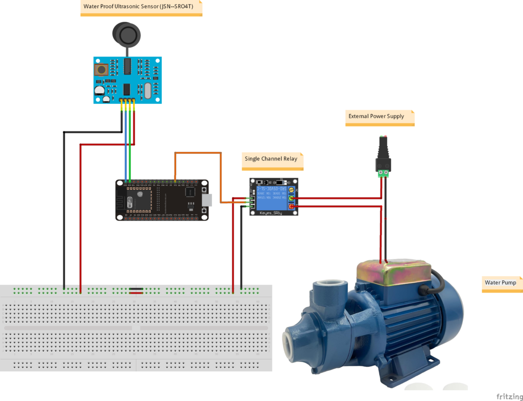
Transform your basic alarm into an advanced water management system by adding automation components. These upgrades can stop overflow automatically or send alerts to your phone.
Add a Relay to Shut Off Water
Connect the output of your transistor circuit to a 5V relay module wired to your water pump power supply. This setup automatically cuts power to the pump the moment the alarm triggers, stopping the flow before overflow occurs.
Integrate with Microcontrollers
Feed your alarm signal into an Arduino or ESP32 board to enable SMS alerts and mobile app monitoring. You can log usage data and receive notifications anywhere via Wi-Fi or GSM modules for total peace of mind.
Safety Rules for All Designs
Protect yourself and your property by following strict safety guidelines when combining electricity and water. Even low voltage systems require careful handling to prevent accidents.
Use Only Low Voltage DC
Stick strictly to power sources between 5V and 12V DC for any circuit involving water probes. Never connect mains voltage like 110V or 220V directly to probes as this creates a severe electrocution hazard.
Isolate and Insulate Connections
Cover every wire joint with heat shrink tubing, silicone sealant, or electrical tape to prevent accidental shorts. Ensure no bare metal is exposed outside the specific sensing tips of your probes.
Disconnect Power Before Maintenance
Always turn off and unplug your system before adjusting probes, cleaning scale, or replacing batteries. Keep all control boxes and batteries in dry shaded areas away from direct water spray and sun exposure.
Frequently Asked Questions About Water Tank Overflow Alarms
What type of probes work best for water sensors?
Stainless steel rods are the best choice because they resist corrosion better than copper wires. You can also use insulated copper wire with only the very tips exposed, but check them regularly for oxidation.
How long will a battery powered alarm last?
A simple transistor circuit drawing zero current when idle can last 6 to 12 months on a standard 9V battery. Systems with continuous monitoring or wireless transmission may require solar charging or more frequent battery changes.
Can I use this alarm with salt water or rain water?
Yes, but rain water is less conductive than tap water so you may need to reduce the gap between probes slightly. Salt water conducts very well so standard probe spacing works perfectly for those applications.
Why is my alarm sounding when the tank is not full?
Condensation on the probes or mineral buildup usually causes false alarms in humid environments. Clean the probes with vinegar and ensure they are angled downward so water droplets run off instead of bridging the gap.
How do I stop the alarm from corroding the probes?
Use stainless steel or gold plated probes instead of standard copper to minimize oxidation over time. Cleaning the probes monthly with vinegar also removes corrosive deposits before they damage the metal.
Key Takeaways for Building Your Water Tank Overflow Alarm
Building a water tank overflow alarm at home is a practical project that saves water and prevents property damage. You can choose from simple transistor circuits, wireless remote systems, or mechanical floats depending on your skill level and needs.
Start with the basic BC547 transistor design if you are new to electronics, or try the wireless solar version for remote monitoring capabilities. Remember to clean your probes regularly and always use low voltage DC power to ensure safety and longevity.