
Your engine runs hot, especially in traffic. The temperature gauge climbs into the red. You pop the hood and see no fan spinning. That’s a classic sign of a coolant fan not working, and ignoring it can lead to catastrophic engine damage in minutes. The radiator fan pulls air through the cooling system when the car isn’t moving fast enough to generate natural airflow. Without it, heat builds up rapidly.
When the coolant fan fails, your engine can overheat within minutes at idle. This isn’t just about comfort. It risks warped cylinder heads, blown head gaskets, or even a cracked engine block. Repair costs can exceed $3,000. The same fan also cools the AC condenser, so a failure often means warm air from the vents when stopped. This guide walks you through every diagnostic step, from quick checks to advanced testing, so you can get your fan running again and protect your engine.
Recognizing Dangerous Overheating Symptoms
Engine Overheats at Idle
If your temperature gauge rises while stopped but drops when driving, the coolant fan isn’t doing its job. At highway speeds, airflow through the grille cools the radiator naturally. But at idle or in traffic, the electric fan must kick in. No fan means no cooling. Overheating under these conditions is a red flag you shouldn’t ignore.
Pro Tip: If the engine cools down when moving but overheats in traffic, the problem is almost always the fan or its control system, not the thermostat or water pump.
No Fan Noise When Hot
Start the engine and let it warm up. When the coolant reaches 195°F to 220°F, you should hear a relay click followed by the whir of the fan motor. Silence means something is wrong. Some vehicles run the fan briefly after shutdown to cool residual heat, which is normal. But no sound when hot indicates a failure.
Visual Cue: Look through the grille. Can you see if the fan blades are turning? Even a slow spin counts. No movement means no cooling.
AC Blows Warm Air at Low Speeds
The same fan cools both the radiator and AC condenser. If the fan isn’t running, refrigerant cannot release heat, leading to poor cooling, especially at idle. If your AC works fine on the highway but turns warm in traffic, suspect the fan.
Warning: High refrigerant pressure from poor condenser cooling can trigger the AC clutch to cycle off, reducing efficiency and wearing components prematurely.
Testing Fuses First

Locate the Correct Fuse
The cooling fan fuse is usually in the underhood power distribution box. Check the fuse diagram on the lid or in your owner’s manual. Labels may read “Radiator Fan,” “Cooling Fan,” “Engine,” or “Ignition.” Most fan fuses are 20A, 30A, or 40A. Use the same amperage when replacing.
Fact: A single fuse often powers both the relay coil and fan motor. A blown fuse kills the entire circuit.
Test with a Multimeter
Do not rely on sight alone. Test both ends of the fuse with a multimeter. Set it to DC voltage and turn the ignition on. A good fuse shows approximately 12V on both terminals. A blown fuse shows voltage on one side only. If the fuse is blown, do not just replace it. A repeated failure means a short circuit in the fan motor, wiring, or relay. Replace the fuse only after diagnosing the cause.
Expert Note: Use a test light or power probe for quick checks, but a multimeter gives precise readings and detects partial failures that visual inspection misses.
Checking the Fan Relay
Identify Relay Terminals
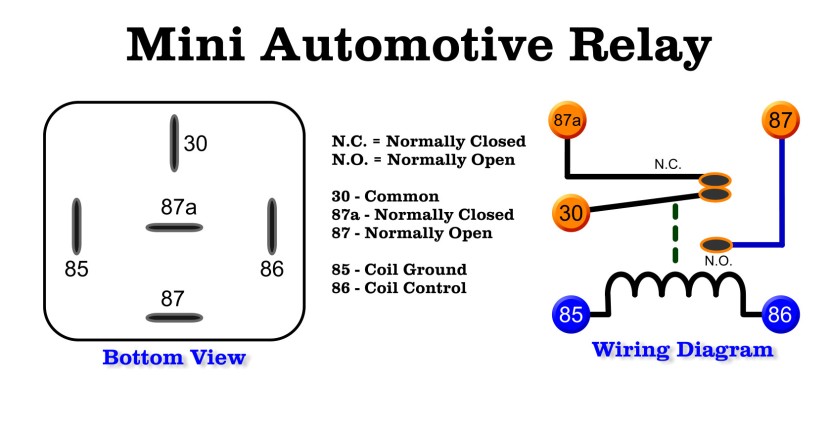
Most relays follow ISO standards. Terminal 30 is battery power, constant 12V. Terminal 85 is control ground from the ECU. Terminal 86 is switched ignition power. Terminal 87 is output to the fan motor. Pull the relay and inspect for melted plastic or burnt contacts.
Check Coil Resistance
Set your multimeter to ohms. Measure between pins 85 and 86. A healthy coil reads 60 to 120 ohms. Infinite resistance means the coil is dead, and you should replace the relay.
Quick Fix: Swap the fan relay with a similar one, like the horn or A/C relay, to test. If the fan works, the relay was bad.
Verify Relay Function
Apply 12V between pin 86 positive and pin 85 negative. You should hear a click. Now check continuity between pins 30 and 87. It should drop to near 0 ohms when energized. No click or no continuity indicates a faulty relay.
Live Test: With the relay installed, probe pin 30 for battery power, pin 86 for ignition power, pin 85 for ECU ground when needed, and pin 87 for output. No output means the relay is not getting the signal or is defective.
Direct Fan Motor Test
Bypass the Circuit
Disconnect the fan motor’s electrical connector. Use jumper wires to connect positive 12V to the fan’s power wire, usually black/red or solid red. Connect negative ground to the motor housing or chassis. If the fan spins freely and quietly, the motor is good. If it does not spin, spins slowly, or makes a grinding noise, the motor has failed.
Key Insight: If the fan runs on direct power but not in the car, the problem is upstream in the relay, fuse, sensor, or wiring.
Assess Motor Condition
Listen for grinding, which indicates worn bearings. Squealing suggests brush failure. Intermittent spinning may indicate an internal short. If the motor draws excessive current or overheats, replace it.
Pro Tip: Clean dirt and debris from blades before testing. A clogged fan may strain the motor and give false readings.
Diagnosing the ECT Sensor
Understand Its Role
The Engine Coolant Temperature sensor tells the ECU when the coolant is hot. If it fails, the ECU never signals the fan to turn on. No temperature reading on your dash is a strong clue the ECT sensor is dead. Common DTCs include P0115, P0117, and P0118.
Test Sensor Resistance
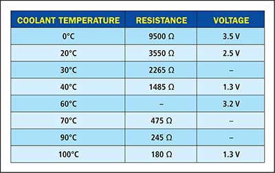
Unplug the sensor. Use a multimeter in ohms mode. Measure resistance across the terminals. At 70°F, expect 2.5 to 3.5 k ohms. At 170°F, expect approximately 0.5 k ohms. At 200°F, expect approximately 0.25 k ohms. Resistance should decrease as temperature increases. No change means the sensor is faulty.
Warning: Aftermarket sensors often fail early. Stick with Denso, Bosch, or Standard Motor Products for reliable performance.
Perform a Jumper Ground Test
Unplug the ECT sensor. Use a jumper wire to ground the signal wire to the chassis. Turn the ignition on but do not start the engine. If the fan turns on, the control circuit is good and the ECT sensor was bad.
Caution: Never drive with the sensor grounded. This tricks the ECU into thinking the engine is overheating, affecting fuel delivery and timing.
Inspecting Wiring and Ground Connections
Trace Power and Signal Wires
Use your multimeter in continuity mode. Test the power wire from the relay to the fan and expect less than 0.5 ohms. Test the ground wire from the fan to the chassis the same way. Test the signal wire from the ECT sensor to the ECU for opens or shorts. Perform a wiggle test on the harness while monitoring resistance. Intermittent faults often show up this way.
Common Issue: Rodents chew wires. Look for exposed copper or frayed insulation.
Verify Ground Connections
A poor ground kills electrical circuits. Test the fan motor housing to battery negative, the ECT sensor body, the relay ground, and the engine block to chassis. A good ground reads less than 0.1 ohms. A bad ground reads more than 1 ohm or shows infinite resistance. Clean corrosion with a wire brush. Use a star washer and stainless bolt for a solid connection.
Fix: Add a dedicated ground strap from the fan assembly to the chassis if the original is compromised.
Testing the Fan Control Switch
Identify the Thermal Switch
Some older vehicles use a fan control switch separate from the ECT sensor. It is usually mounted on the radiator or coolant housing and activates at a set temperature, such as 195°F.
Test for Continuity
Disconnect the switch. With the engine cold, test for continuity. It should be an open circuit. As the engine warms, it should close and allow current to flow.
Bench Test: Remove the switch and place it in hot water with a thermometer. At the rated temperature, it should switch from open to closed. No continuity when hot means replace the switch.
Note: A failed switch can mimic ECT sensor issues. Always verify which system your vehicle uses before replacing parts.
Using OBD2 Scanner for Live Data
Pull Relevant DTCs
Connect an OBD2 scanner. Look for P0115 through P0119 for ECT sensor circuit issues. P0480 through P0483 indicate fan control circuit faults. U-codes show module communication errors. These codes point directly to the problem area.
Monitor Live ECT Readings
Compare the scanner’s live ECT reading with the actual temperature, using an infrared thermometer on the radiator hose. If the scanner reads negative 40°F or 300°F, the sensor or wiring is bad.
Expert Move: Watch the fan command status. If the ECU says “Fan ON” but nothing happens, the issue is in the power circuit, meaning the relay, fuse, or motor.
Force Fan Activation
If your scanner supports bi-directional control, command the fan to turn on. If it spins, the power circuit is good and the fault was upstream in the sensor or software. If it does not spin, the problem is downstream in the relay, fuse, or motor.
Rare Fix: Some vehicles need a software update if fan logic is corrupted. Check for Technical Service Bulletins.
Replacing Faulty Components
When to Replace the Fan
Replace the fan motor if it fails the direct 12V test, blades are cracked or wobbly, bearings make grinding noise, or it draws excessive current. Choose an OEM or OE-equivalent assembly. Avoid cheap universal kits with undersized motors.
Time Estimate: Plan for 1 to 2 hours for most vehicles.
Choose Quality Sensors and Relays
Use Denso, Bosch, or Standard Motor Products for ECT sensors. For relays, pick Omron, Tyco, or Bosch. They handle thermal cycling better than cheap alternatives.
Warning: Low-quality aftermarket parts fail fast. Spend a little more for reliability and avoid repeat repairs.
Repair Wiring Properly
Cut out damaged sections. Splice in 14 to 16 AWG wire for power and 18 to 20 AWG for signals. Use crimp connectors with heat-shrink tubing. Never use solder-only repairs. Route new wire away from heat and moving parts.
Pro Tip: Apply dielectric grease to connectors to prevent future corrosion.
Preventing Future Fan Failures
Annual Cooling System Check
Inspect fan blades and shroud for cracks. Check electrical connectors for tightness and corrosion. Clean radiator fins for debris using water or air. Replace relays and fuses preventively on vehicles over 10 years old.
Lifespan Guide: Fan motors typically last 80,000 to 150,000 miles. ECT sensors last around 100,000 miles. Relays last 10 or more years.
Monitor Temperature Daily
Make it a habit to check the temperature gauge, especially in traffic. A sudden rise means act fast. Pull over and let the engine cool.
Final Warning: Never drive long distances with a failed coolant fan. Even 10 minutes of overheating can warp metal and ruin your engine permanently.
Frequently Asked Questions About Coolant Fan Not Working
How do I know if my coolant fan is not working?
Look for a rising temperature gauge at idle, no fan noise when the engine is hot, and warm AC air at low speeds. The most obvious sign is steam or smoke from under the hood during traffic stops.
Can I drive with a non-working coolant fan?
Driving short distances at low speeds with a failed fan risks engine overheating and severe damage. If the fan is not working, have it diagnosed immediately. Driving on highways with natural airflow may be safe temporarily, but the risk remains.
What causes a coolant fan to stop working?
The most common causes are a blown fuse, defective relay, failed ECT sensor, bad fan motor, wiring issues, or poor ground connections. Systematic testing identifies which component is at fault.
How much does it cost to fix a coolant fan not working?
Costs vary by cause. A fuse or relay costs under $30. An ECT sensor runs $50 to $150. A fan motor ranges from $100 to $400. Professional diagnosis may add $100. Major repairs can reach $500 or more if the engine sustains damage.
Will my engine be damaged if the fan fails while driving?
Yes, prolonged overheating from a failed fan can warp cylinder heads, blow head gaskets, and crack engine blocks. The damage can require engine rebuilds costing $1,500 to $5,000 or more. Immediate action prevents costly repairs.
Can I test the fan motor directly at home?
Yes, disconnect the fan connector and apply 12V power directly using jumper wires from a battery. If the fan spins freely and quietly, the motor is good. If it does not spin or makes grinding sounds, replace the motor.
Key Takeaways for Fixing a Coolant Fan Not Working
A coolant fan not working is a critical issue that demands immediate attention. Start with the simplest checks: inspect fuses and test the relay. If those pass, move to the ECT sensor and direct motor testing. Always diagnose before replacing parts to avoid wasting money on unnecessary components. Use quality OEM parts for sensors and relays to ensure long-term reliability. Finally, establish a maintenance routine that includes annual cooling system inspections and temperature monitoring. With the right approach and this guide, you can identify the problem accurately and get your cooling system working properly again.