A poorly executed tank overflow design can lead to catastrophic spills, vacuum collapse, or wasted water resources. Whether you manage potable water or industrial fluids, incorrect sizing risks safety and environmental compliance.
This guide details how to size pipes correctly, prevent syphoning, and integrate overflows into sustainable landscapes. You will learn to apply standards like AWWA D100 and Norsok P-001 for reliable results.
Match Inlet Pipe Size or Larger
A foundational rule in tank overflow design is simple. The overflow line should be at least as large as the largest inlet pipe or one size bigger.
Follow Norsok P-001 Sizing Rule
Codified in Norsok Std P-001 Section 6.1, this standard prevents overfilling by ensuring the tank discharges peak inflow rates.
* If a tank receives 300 gpm through a 12-inch inlet, the overflow must be NPS 12 or NPS 14.
* This rule applies across potable water, industrial, and rainwater systems.
* It serves as a conservative benchmark that avoids complex calculations during initial design.
Avoid Undersizing Risks
Undersized overflows create dangerous lag between inflow and outflow. Even a small reduction can restrict flow by over 30 percent.
* Overflow delays cause unintended tank pressurization.
* Spills occur frequently during rapid fill events.
* Always verify inlet flow rates before finalizing overflow diameter.
Use Weir Boxes for Predictable Flow
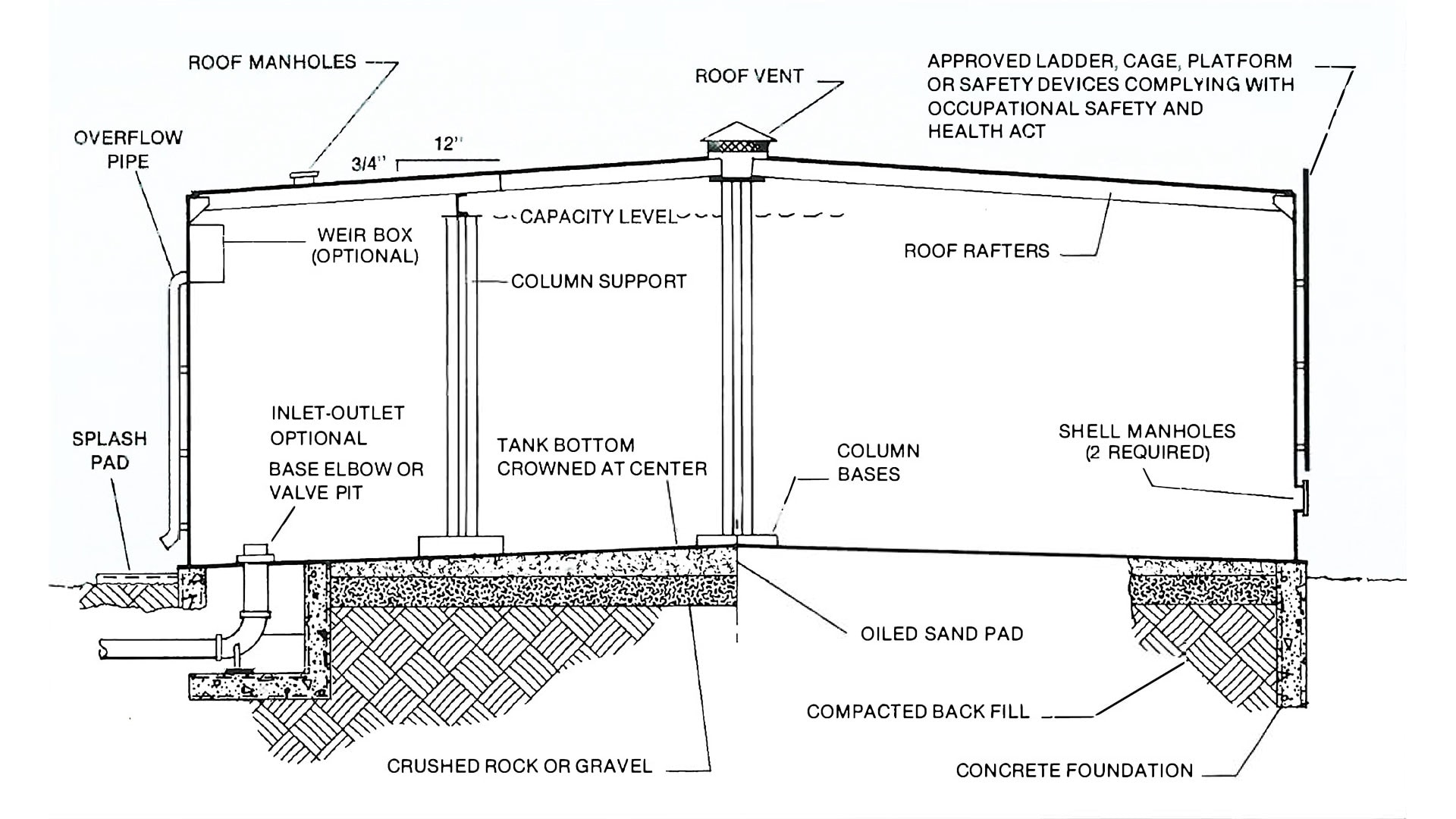
For potable water tanks, the weir box method per AWWA D100 is the gold standard. The weir box acts as a controlled spill point to ensure full pipe flow.
Size for 6-Inch Head Rise
Design the weir so water rises no more than 6 inches above the weir crest at peak overflow rate.
* This small head ensures the tank does not overpressurize.
* It maintains predictable discharge without vortexing.
* The design prevents air locks within the system.
Calculate Flow Using Orifice Equation
Treat the overflow as an orifice once weir dimensions are set. Use Bernoulli-based orifice flow equations to determine capacity.
* Set the discharge coefficient between 0.6 and 0.8.
* Calculate cross-sectional area of the weir opening.
* Limit head above the weir to a maximum of 0.5 feet.
Size Downstream Pipe Conservatively
Size the discharge pipe assuming atmospheric discharge after calculating weir flow. Include friction losses from fittings and pipe length.
* Ensure total head loss is less than the vertical drop.
* Increase pipe diameter if losses exceed available head.
* Reduce elevation difference if pipe sizing cannot change.
Prevent Syphoning With Proper Sizing
Syphoning in industrial tanks can cause erratic flow or vacuum collapse. You must ensure the outlet remains flooded under peak conditions.
Apply Hills Equation 3 for Flooded Flow
Use Hills Equation 3 to calculate the required liquid height above the outlet. This ensures sufficient submergence to maintain full flow.
* Measure the design flow rate accurately.
* Use the internal diameter of the upstream pipe.
* Apply gravitational acceleration constants correctly.
Measure h at Static Level, Not Nozzle
A common error involves measuring liquid height at the nozzle where the surface dips. Always measure away from the outlet where the surface is flat.
* Misreading this leads to undersizing.
* Syphon break failure occurs with incorrect measurements.
* Static level measurement ensures accurate head calculation.
Ensure Self-Venting Downleg
The pipe section after the syphon break must allow air to escape. Size the downleg so the Froude number stays below 0.31.
* This prevents air from being sucked back into the break.
* Disrupted flow causes operational instability.
* Proper sizing maintains consistent hydraulic performance.
Avoid Negative Pressure Collapse
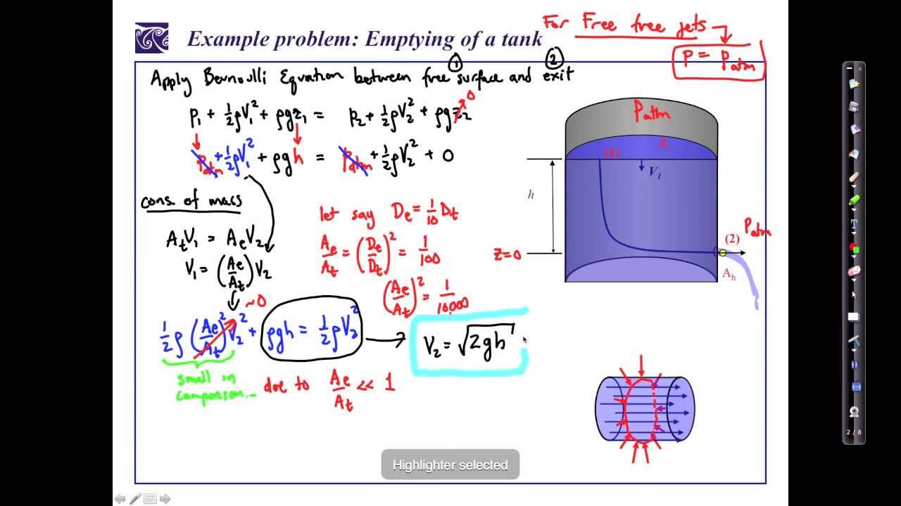
Long vertical overflow drops can create vacuum conditions if not analyzed properly. Use Bernoulli’s equation to verify absolute pressure limits.
Check Bernoulli Profiles on Vertical Drops
Calculate velocity, elevation, and pressure heads at each point for pipes dropping 20 feet or more.
* Pressure below 0.5 psia may cause pipe collapse.
* Intermittent flow results from vacuum formation.
* Add a vent line above the syphon break to solve this.
Install Syphon Breaks Correctly
An open syphon break prevents full syphon formation but requires specific installation criteria.
* Place it above the maximum liquid level.
* Vent to atmosphere unless contents are toxic.
* Size so the downleg remains self-venting.
Control Vortexing and Air Entrainment

Vortexing at the overflow inlet pulls air into the pipe. This reduces effective flow by up to 50 percent and disrupts system efficiency.
Install Anti-Vortex Plates
A horizontal anti-vortex plate disrupts rotational flow. It promotes full pipe discharge when mounted over the inlet.
* Plates increase entrance loss under orifice flow.
* Use only when head is sufficient to maintain flow.
* Added resistance requires careful hydraulic verification.
Use Downward-Facing Inlets
Orienting the overflow inlet downward submerges the entry point. This minimizes surface disturbance and vortex formation effectively.
* Combine with a stilling chamber for best results.
* Baffle walls reduce turbulence significantly.
* This method works well in high-flow scenarios.
Increase Submergence Depth
Increase the static head above the inlet if vortexing persists. More submergence raises the energy barrier for vortex formation.
* Maintain at least 1.5 times the pipe diameter.
* Higher head prevents air ingestion reliably.
* Simple geometry changes often solve complex flow issues.
Handle Multi-Phase and Pressurized Tanks
Oil-water separation tanks and blanketed vessels require special attention. Density differences and internal pressure affect overflow hydraulics significantly.
Account for Oil-Water Density Differences
The overflow upleg may contain lighter fluid like oil. This reduces hydrostatic pressure and requires a higher tank level to initiate flow.
* Calculate effective head using weighted average density.
* Ignore this at your own risk in fuel tanks.
* A 10 cm oil layer changes equivalent water head.
Design for Blanket Pressure
Tanks blanketed with natural gas have positive internal pressure. This affects the liquid level needed to initiate overflow.
* Blanket pressure increases discharge head.
* Adjust calculations to include gauge pressure.
* Never vent flammable gases to the atmosphere.
Choose Internal vs. External Piping Wisely
Piping location impacts maintenance access and long-term reliability. External routing is generally preferred for most site-fabricated tanks.
Prefer External for Maintenance
External overflow piping allows easier access for inspection and cleaning. It simplifies future maintenance tasks significantly.
* Painting becomes much easier externally.
* Repair work avoids confined space entries.
* Visual inspection detects issues before failure.
Accept Internal Only When Necessary
Internal piping is sometimes used in shop-fabricated tanks. Accept it only if process requirements dictate this configuration.
* Freeze protection may require internal routing.
* Toxic contents need sealed routing solutions.
* Ensure internal pipes are coated for corrosion resistance.
Integrate Overflow Into Landscape Design
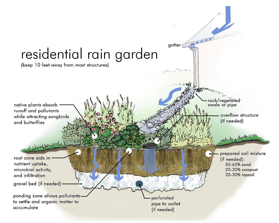
In residential and farm rainwater systems, overflow is a resource. Design the discharge to feed swales that slow and soak water into soil.
Route to Swales and Rain Gardens
Design discharge to feed shallow vegetated ditches called swales. Each swale fills sequentially and spills gently to the next.
* Rock-lined spillways prevent erosion effectively.
* This method recharges groundwater naturally.
* Excess flow becomes a regenerative resource.
Use Rock Spillways to Control Flow
Install rubble spillways or stone weirs at the overflow discharge point. These structures dissipate energy and spread flow.
* Prevent gully formation with proper rock sizing.
* Use locally available rock for cost efficiency.
* Natural-looking control blends with the environment.
Support Pioneer and Guild Species
Plant hardy pioneer species like Acacias to stabilize slopes. Their deep roots bind soil and build organic matter over time.
* Introduce productive trees once established.
* Select species based on sun exposure and soil type.
* Test species in small trials before full planting.
Test and Verify System Performance
No model replaces real-world testing during actual rain events. Observe flow patterns and adjust your tank overflow design as needed.
Conduct Real Rain Event Trials
Watch when overflow begins and how flow moves through swales. Look for signs of erosion or pooling during the first major rain.
* Adjust spillway height if erosion occurs.
* Add check dams to slow water velocity.
* Monitor plant response to intermittent flooding.
Inspect for Air Locks and Blockages
Inspect the overflow line for debris buildup after installation. Check for air pockets and corrosion or scaling issues.
* Clean systems annually to maintain capacity.
* Algae-prone water requires frequent attention.
* Early detection prevents catastrophic failure.
Frequently Asked Questions About Tank Overflow Design
What is the standard rule for sizing overflow pipes?
The overflow line should match the largest inlet pipe size or be one size larger. This follows the Norsok P-001 standard for safe discharge.
How do you prevent syphoning in overflow lines?
Ensure the outlet remains flooded by using Hills Equation 3 for sizing. Maintain a self-venting downleg with a Froude number below 0.31.
Why use a weir box for potable water tanks?
Weir boxes provide a controlled spill point with a maximum 6-inch head rise. This ensures predictable flow and prevents air entrainment.
Can overflow water be used for irrigation?
Yes, routing overflow to swales and rain gardens turns excess water into a resource. This approach supports landscape hydration and prevents erosion.
What causes negative pressure in vertical overflow drops?
High velocity in long vertical drops can create vacuum conditions. Always check pressure profiles using Bernoulli’s equation to prevent collapse.
Key Takeaways for Effective Tank Overflow Design
Proper tank overflow design balances engineering rigor with practical adaptability. Matching inlet sizes, preventing syphoning, and integrating landscape features ensure system reliability.
Apply hydraulic principles and adhere to standards like AWWA D100. Your overflow system can become a functional asset rather than just a safety mechanism.
Start by reviewing your current inlet sizes and verifying head calculations. Implement these changes to protect your facility and conserve water resources today.