
A failing coolant temperature sensor can silently wreck your engine’s performance, fuel economy, and emissions, often without triggering the check engine light. This small but critical component feeds the engine control unit (ECU) temperature data that controls fuel mixture, idle speed, cooling fans, and ignition timing. When it malfunctions, your car may run rich, stall, overheat, or fail emissions testing. Knowing how to check a coolant temp sensor gives you the power to diagnose this issue quickly and avoid costly repairs. In this guide, you’ll walk through every diagnostic step, from voltage testing to live data monitoring, using simple tools you likely already have.
Locate the Coolant Temperature Sensor on Your Engine
The coolant temperature sensor threads directly into the engine block, cylinder head, or thermostat housing. You’ll find it most commonly where the upper radiator hose connects to the engine, or on the front or side of the block.
Finding the Sensor Quickly
Look for a small component resembling a screw with one or two electrical wires leading to a connector. It typically has a metal or plastic body and sits in plain view on many vehicles. Use a drop light to improve visibility under the hood.
If the sensor is hidden behind other components, consult your vehicle’s repair manual or search online for “[Year, Make, Model] coolant temp sensor location” to find diagrams or videos specific to your vehicle.
Prepare Safely Before Testing
Working on a hot cooling system causes serious burns and releases pressurized coolant. Always let the engine cool completely for at least 2 to 3 hours before beginning any testing.
Cold Engine Requirements
Never open the radiator cap on a warm engine. If you need to drain slightly coolant to prevent spillage during sensor removal, do so carefully into a clean container. For accurate baseline resistance readings, allow the engine to stabilize at ambient temperature around 20°C or 68°F.
Disconnect the negative battery terminal before testing to prevent electrical shorts and protect your multimeter.
Test Reference Voltage at the Connector

Before replacing the sensor, verify the ECU actually sends proper power. Many “dead” sensors are actually victims of missing voltage or ground.
Checking ECU Power Supply
Turn the ignition OFF and unplug the sensor’s electrical connector. Set your digital multimeter to DC volts on the 20V range. Insert the red probe into the signal wire terminal and the black probe into a solid ground such as the engine block or battery negative. Turn the ignition to “ON” with the engine off, then read the voltage.
You should see 4.8V to 5.1V, which is the standard reference voltage. If you get no voltage, check fuses related to the engine control module and inspect the wiring harness for cuts, corrosion, or loose connections. The problem may lie in the ECU or wiring rather than the sensor itself.
Verify Ground Circuit Continuity
A broken ground connection renders the sensor useless even when voltage is perfect. Testing ground continuity takes seconds and rules out a common failure point.
Testing Ground Connection
Keep the black multimeter probe on engine ground and switch the meter to continuity mode. Touch the red probe to the ground terminal in the harness connector. A continuous beep indicates solid ground. No beep means you have an open circuit that requires tracing the ground wire for breaks, corrosion, or poor contact.
High resistance in the ground circuit causes erratic readings even when continuity seems present, so don’t skip this step.
Remove and Test Sensor Resistance
Resistance testing provides the most reliable verification of sensor health. This test compares your readings against manufacturer specifications to confirm the thermistor inside functions properly.
Measuring Ohms at Room Temperature
Use a 19mm or 3/4-inch wrench to remove the sensor. Have a towel or drain pan ready for minor coolant seepage. Set your multimeter to resistance mode on the 20k or 200k ohm range. Place one probe on the signal terminal and the other on the ground terminal or metal body. Record the reading at room temperature around 20°C or 68°F.
At 68°F, acceptable resistance falls between 31,700 and 42,900 ohms. Some sources list 29,100 ohms as acceptable due to manufacturer tolerances. If your reading shows infinite resistance or OL, you have an open circuit and need to replace the sensor. If it reads zero or near-zero ohms, you have a short circuit. Readings outside the range that don’t respond to temperature changes indicate a faulty thermistor.
Perform Hot Water Resistance Test
Static resistance testing tells you part of the story. Dynamic testing confirms the sensor reacts properly to actual temperature changes, which is exactly what it does in your engine.
Watching Real-Time Response to Heat
Fill a heat-safe container with water and submerge the sensor tip while keeping the electrical connector completely dry. Insert a digital thermometer into the water and measure initial resistance at room temperature. Gradually heat the water and record resistance every 10 to 20°C.
The sensor uses an NTC thermistor, meaning resistance must decrease as temperature increases. At 20°C you should see around 31,700 to 42,900 ohms. At 50°C expect 10,000 to 15,000 ohms. At 82°C look for 5,000 to 6,000 ohms. At 100°C resistance drops to approximately 1,760 to 2,380 ohms.
A healthy sensor shows a smooth, steady drop in resistance. No change, erratic spikes, or infinite readings mean the sensor has failed. Avoid letting the sensor touch the pot bottom during testing, as direct metal contact skews your readings.
Monitor Live Data with OBD-II Scanner
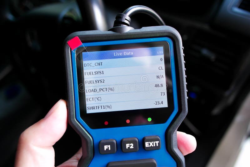
Live data monitoring catches intermittent issues that resistance testing might miss. This real-time view shows exactly what the ECU sees during engine operation.
Validating Sensor Behavior in Real Time
Plug your OBD-II scanner into the port under the dashboard and turn the ignition to ON without starting the engine. Access Live Data and find Engine Coolant Temperature. The starting value should match ambient air temperature. Start the engine and monitor the temperature rise over 10 to 15 minutes.
Normal behavior shows the cold start matching outside temperature, a warm-up rate of approximately 2 to 5°F per minute, and reaching operating range of 185 to 221°F within 15 minutes. On a 5V system, voltage drops from around 4.5V when cold to 0.5V when hot.
Red flags include a reading stuck at -40°F indicating an open circuit, a reading jumping to 300°F or higher indicating a short to ground, or erratic fluctuations pointing to a loose connection or failing sensor. Use an infrared thermometer on the engine near the sensor to confirm actual temperature matches what the scanner displays.
Diagnose Common Failure Patterns
Matching symptoms to test results speeds up your diagnosis. Use this reference guide to interpret what you’re seeing.
Matching Symptoms to Sensor Faults
Poor fuel economy and black exhaust smoke indicate the sensor is stuck cold, causing the ECU to constantly enrich the fuel mixture. Hard starting when the engine is hot points to faulty hot resistance readings. Overheating or false overheat warnings mean the sensor fails to trigger cooling fans properly.
A check engine light with codes P0117 or P0118 indicates low or high input from a short or open circuit. Idle speed that doesn’t drop after warm-up means the ECU thinks the engine is still cold. A temperature gauge reading low or static may indicate a dual-sensor issue where the gauge sensor differs from the ECU sensor.
Replace the Sensor If Faulty
If testing confirms failure, replacement is straightforward and takes most DIY mechanics under an hour.
Installing a New Unit Correctly
Ensure the engine is cool, then drain coolant slightly below the sensor level if needed. Disconnect the electrical connector and remove the old sensor with a 19mm wrench. Inspect the threads and clean any debris. Apply coolant-resistant sealant or thread tape only if your manual specifies it, as many sensors come with pre-installed O-rings.
Install the new sensor and tighten to 10 to 25 Nm, checking your manual for the exact specification. Reconnect the wiring, refill coolant, and bleed any air from the system. Clear DTCs using your OBD-II scanner. Compare the resistance of your old sensor to the new one before installation to ensure you didn’t receive a defective part.
Verify Repair and Reset System
After replacement, validating full system recovery confirms your fix worked correctly.
Confirming the Fix Works
Start the engine and monitor warm-up behavior. Use your OBD-II scanner to confirm the ECT reading climbs steadily and reaches normal operating temperature. Verify cooling fans activate at the correct temperature, typically 210 to 230°F. Check fuel trims; both short-term and long-term fuel trims should stabilize within plus or minus 10%.
Road test the vehicle under load on highways or hills. Inspect for coolant leaks around the new sensor. Record live data before and after repair for future comparison.
Prevent Future Failures
A failed sensor often signals broader cooling system neglect. Proper maintenance extends sensor life and prevents repeat failures.
Extending Sensor Longevity
Flush coolant every 30,000 to 60,000 miles using the correct type for your vehicle, whether OAT, HOAT, or IAT. Never mix coolant colors. Inspect the connector for moisture, corrosion, or bent pins during routine oil changes. Avoid electrolysis by ensuring clean, tight engine grounds.
Most ECT sensors last 80,000 to 150,000 miles with proper maintenance. Use OEM or high-quality aftermarket sensors rather than cheap units that fail prematurely.
When to Suspect the ECU or Wiring
If a new sensor doesn’t fix the problem, look deeper into the electrical system.
Ruling Out Bigger Issues
Investigate further if your new sensor shows no reference voltage, if resistance is correct but the ECU reads -40°F, or if the same DTC returns immediately after clearing. Possible causes include damaged wiring harness from chaffing, pinching, or corrosion, poor ECU ground, or a faulty ECU output.
Use a wiring diagram to test continuity from sensor to ECU. Consider professional diagnostics if issues persist despite thorough testing.
Key Takeaways for Testing Your Coolant Temp Sensor
Testing a coolant temperature sensor takes under an hour with a $20 multimeter and basic OBD-II scanner. The process involves verifying proper 5V reference voltage from the ECU, confirming solid ground connection, measuring resistance at room temperature against specifications, performing a hot water test to verify the NTC thermistor responds to temperature changes, and monitoring live data to see real-world performance.
Always compare readings to your vehicle-specific specifications rather than generic values. Replace with OEM or quality aftermarket parts, and clear DTCs after installation. This diagnostic skill pays off every time you turn the key, whether you’re chasing a rough idle or preparing for an emissions test.
Frequently Asked Questions About Checking a Coolant Temp Sensor
How do I know if my coolant temperature sensor is bad?
Common signs include poor fuel economy, black exhaust smoke, hard starting, engine overheating, erratic idle, and a check engine light with codes P0117 or P0118. The temperature gauge may also read incorrectly or stay static.
Can I test my coolant temp sensor without removing it?
Yes. You can back-probe the connector to check reference voltage and ground continuity without removal. For resistance testing, the sensor must be removed. Live data monitoring works with the sensor installed.
What should the resistance be at room temperature?
At approximately 20°C or 68°F, a healthy sensor reads between 31,700 and 42,900 ohms. Values outside this range, especially infinite resistance or near-zero ohms, indicate failure.
Will a bad coolant temp sensor cause my engine to overheat?
Yes, because the sensor controls cooling fan activation. If it fails to report rising temperatures, the fans may not turn on, leading to overheating. However, the sensor can also fail in ways that cause false overheat warnings.
How much does it cost to replace a coolant temperature sensor?
Sensor costs range from $20 to $80 for OEM quality. DIY replacement takes 25 to 50 minutes. Professional labor adds $50 to $150, bringing total replacement cost to $100 to $300 on average.
Can I drive with a bad coolant temp sensor?
Driving is not recommended. A malfunctioning sensor causes incorrect fuel mixtures that lead to poor performance, increased emissions, and potential engine damage. Replace it before driving further.